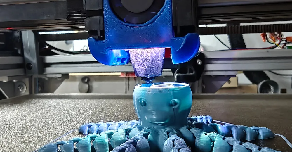
With adhesion working, print time became interesting. The starting point was 1 h 41 m 21 s. The per-feature breakdown immediately showed where the time went:
| Feature | Time | Share | Avg. flow |
|---|---|---|---|
| Outer wall | 32 m 53 s | 32.4 % | 4.2 mm³/s |
| Non-extruding | 30 m 47 s | 30.4 % | – |
| Inner wall | 20 m 13 s | 19.9 % | 8.4 mm³/s |
| Solid infill | 10 m 10 s | 10.0 % | 12.5 mm³/s |
| Sparse infill | 4 m 50 s | 4.8 % | 9.3 mm³/s |
For almost a third of the time nothing is extruded. With eighty separate islands per layer and 124 layers, that is roughly nine thousand travel moves. And the outer wall ran at 4.2 mm³/s – a fraction of what the hotend can do. The limit there was not flow but speed.
The most expensive finding: Z-hop
A look at the machine limits explains the thirty percent:
machine_max_acceleration_z: 300 # mm/s^2The Z axis moves the bed and accelerates correspondingly slowly. A 0.2 mm lift therefore costs about a tenth of a second – not because of the distance, but because of accelerating and decelerating. Nine thousand times.
| Z-hop | Total time | Extra cost | Protection |
|---|---|---|---|
| off | 3713 s | – | none |
| 0.1 mm, Auto | 3950 s | +237 s | half |
| 0.1 mm, Slope | 3944 s | +231 s | half |
| 0.2 mm, Slope | 3986 s | +273 s | full |
“Slope” blends the lift diagonally into the travel move instead of stopping, lifting, travelling and lowering. For 42 seconds extra compared to the half lift you get the full lift height – with a model made of eighty loose chain links, that is the right side of the trade. Turning Z-hop off completely would have saved four minutes and dragged the nozzle over loose links nine thousand times.
The levers in order of impact
| Change | Saving | Reason |
|---|---|---|
| Layer height 0.28 → 0.32 | ~12 min | 124 instead of 142 layers; joints checked beforehand |
| Outer wall 40 → 100 mm/s | ~7 min | small perimeters from 50 % to 85 % |
| Flow 15 → 26 mm³/s | ~5 min | inner wall was flow-limited, not speed-limited |
| Gyroid → Lightning | 4 m 13 s | measured directly: 273 s → 20 s infill time |
| Z-hop Auto → Slope | ~2.5 min | lift blended into the travel move |
| Retraction 30 → 45 mm/s, shells 4→3 / 3→2 | ~2 min | – |
At some point speed stopped helping: raising the outer wall from 90 to 130 mm/s saved 3 % of time, the inner wall even got marginally slower. With eight-millimetre barrels, acceleration is the limit, not speed – and that is where turning numbers stops paying off.
Ad · Affiliate link – if you buy through it, I may earn a commission. It doesn’t change the price for you.

I had noted a caveat: OrcaSlicer calculates with the jerk from the machine profile (9 mm/s), while Klipper ran with square_corner_velocity: 5 – so the real time should be above the estimate.
The caveat was the wrong way round. The estimate was a minute and a half on the safe side. 1 h 41 m became a real 1 h 06 m – 34 % less.
Only probe where you print
The octopus occupies 120 × 120 mm. The mesh probed 388 × 320 mm – a good ten times more area than is printed, with 169 points.
Klipper can derive this itself via BED_MESH_CALIBRATE ADAPTIVE=1, but only if the EXCLUDE_OBJECT_DEFINE lines appear in the G-code before the start macro. That could not be checked without downloading the entire G-code file, so I chose the approach that does not depend on the order: the slicer passes the footprint as a parameter, and the macro calculates area and point count from it.
# machine_start_gcode in OrcaSlicer
START_PRINT HOTEND=[nozzle_temperature_initial_layer] BED=[bed_temperature_initial_layer_single] \
  MESH_MIN={first_layer_print_min[0]},{first_layer_print_min[1]} \
  MESH_MAX={first_layer_print_max[0]},{first_layer_print_max[1]}

# im Makro: Rand, Klemmung auf den konfigurierten Bereich,
# Referenzpunkt immer enthalten, Punktzahl aus der Fläche
{% set m = 5.0 %}
{% set x0 = [[params.MESH_MIN.split(',')[0]|float - m, zx]|min, cfg.mesh_min[0]|float]|max %}
{% set x1 = [[params.MESH_MAX.split(',')[0]|float + m, zx]|max, cfg.mesh_max[0]|float]|min %}
{% set nx = [[(((x1 - x0) / 25.0)|round(0,'ceil')|int) + 1, 3]|max, cfg.probe_count[0]]|min %}
BED_MESH_CALIBRATE MESH_MIN={x0},{y0} MESH_MAX={x1},{y1} PROBE_COUNT={nx},{ny}
The important part is the one that is easily forgotten: setting only MESH_MIN/MESH_MAX achieves nothing – Klipper then still probes 13×13 points, just closer together. The point count has to change too.
| Case | Result | Safeguard |
|---|---|---|
| Object centred | 7×7 = 49 points | – |
| Part in the corner | 9×6 = 54 | area extended to the reference point |
| Part below mesh_min y | 6×6 = 36 | clamped to 84, no Klipper error |
| Part larger than the mesh | 13×13 = 169 | clamped to the configured limits |
| Parameters missing | 13×13 = 169 | plain BED_MESH_CALIBRATE |
The reference point must lie within the probed area – otherwise the mesh has no valid zero reference.
And then it did nothing
The first test run with exactly the command the macro issues produced a mesh over the entire bed. 13×13 points, as always. No error, no warning, response ok.
The reason was in four lines that belong to the Eddy installation and override Klipper's original command:
[gcode_macro BED_MESH_CALIBRATE]
rename_existing: BTT_BED_MESH_CALIBRATE
gcode:
BTT_BED_MESH_CALIBRATE METHOD=rapid_scan # <- kein {rawparams}The wrapper calls the original with a fixed parameter and passes nothing through. MESH_MIN, MESH_MAX and PROBE_COUNT were discarded – no error, no hint. The next print would simply have looked no different.
This is exactly what a test run protects against and a code review does not: the command was correct, the syntax was correct, the response was ok. Only the result was the old one. An error that reports itself as success can only be told apart from success by its result.
The fix passes everything through and keeps the original behaviour when nobody supplies their own METHOD:
{% if 'METHOD' in (rawparams|upper) %}
  BTT_BED_MESH_CALIBRATE {rawparams}
{% else %}
  BTT_BED_MESH_CALIBRATE METHOD=rapid_scan {rawparams}
{% endif %}
After the fix, the test run confirms what was intended: 49 points over 135–265 mm, mean +0.005 mm, 19 of the 49 points negative. So the zero reference holds within the partial area as well.
And the side effect is the actual gain: because the point count grows with the area, the point spacing drops from 32.3 to 21.6 mm. You probe less and finer at the same time.
Is a finer mesh worth it?
If adaptive probing already improves resolution – would even finer be even better? That can be measured rather than estimated, because 7×7, 5×5 and 3×3 are exact subsets of a 13×13 grid. You interpolate from the coarse points and compare with the actually measured fine ones.
| Grid | Points | Spacing | RMS error | Max error |
|---|---|---|---|---|
| 7×7 | 49 | 64.7 mm | 0.0067 mm | 0.0130 mm |
| 5×5 | 25 | 97.0 mm | 0.0077 mm | 0.0191 mm |
| 4×4 | 16 | 129.3 mm | 0.0122 mm | 0.0223 mm |
| 3×3 | 9 | 194.0 mm | 0.0192 mm | 0.0371 mm |
Even with only every second point, the error is 6.7 µm. But that alone is not a sufficient argument: maybe there is real structure there that should be captured. Hence the second question – is this fine structure reproducible at all? Two independent surveys of the same bed, split into the part a coarse grid already sees and the rest:
| Component | Magnitude |
|---|---|
| Bed warp | 108 µm |
| Stored offset | 100 µm |
| Fine structure | 5.5 µm |
| of which real | 2.7 µm |
Of the fine structure that a 13×13 grid captures in addition to 7×7, half is different from one measurement to the next. A finer mesh does not capture more bed shape but bakes a different noise pattern into the correction on every print.
Measured against a 0.32 mm first layer: bed warp accounts for 33.8 % – that is what the mesh is for, and a coarse grid captures it completely. The reproducible fine structure accounts for 0.9 %. A stored Z offset that sat unnoticed in the configuration at the time was, at 100 µm, thirty-seven times larger than that.
That is the real lesson of this calculation, and it applies far beyond bed meshes: before increasing the resolution of a measurement, it pays to check whether the biggest error is in that measurement at all. Here it was somewhere else – in a number that had sat unnoticed in a text file for months.
On top of that, mesh_pps: 5 inserts five interpolated points between every two measured ones anyway. The applied correction surface is already smooth and dense; more probe points only make it jumpier. If you really want to improve accuracy, increase samples – that fights the noise instead of sampling it.
Printer: HevORT, Klipper v0.13.0-743, BTT Eddy USB, Phaetus Rapido 2, 0.4 mm nozzle. Slicer: OrcaSlicer 2.4.2. Profile: PLA on PEI, 0.32/0.32 mm, 230/60 °C, 26 mm³/s, 8 % Lightning, Z-hop 0.2 mm Slope.
All numbers come from measurements on this machine. They apply to this printer and this model, not in general.
This series
One evening of troubleshooting a chain octopus produced four topics that can be read independently:
- Klipper Bed Mesh: A Missing Zero Reference Costs 0.14 mm
- Print-in-Place: Layer Height Decides Whether Joints Move
- OrcaSlicer & Klipper: 34 % Less Print Time – this article
- Seven Fallacies in Klipper Troubleshooting
Ad · Affiliate link – if you buy through it, I may earn a commission. It doesn’t change the price for you.