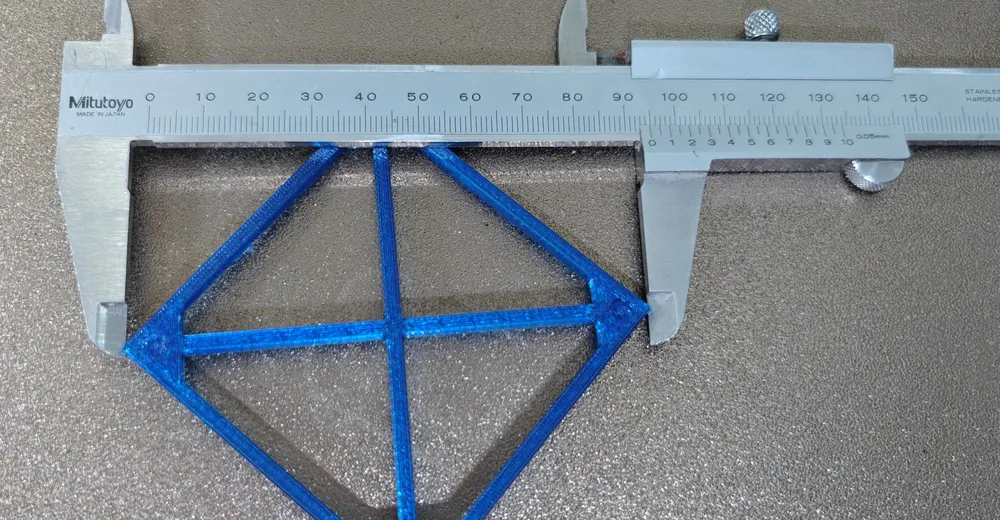
The same test frame twice, 68 × 68 mm with a diagonal cross, measured from outer corner to outer corner. On the first one the diagonals differ by half a millimetre: the frame is not a square but a parallelogram. On the second they match to the hundredth – AC = BD = 95.15 mm.
The backstory is in the article about the two Y endstops fighting each other during homing. Since the second switch was disabled, nothing pulls the X gantry square anymore. So the question was: how skewed is it – and can that be compensated in software?
Skewed is not rotated
The obvious hope: if the gantry is not exactly square, the part simply lies slightly rotated on the bed but stays dimensionally accurate in itself. That is not true, and the reason is simple.
The Y direction is defined by the two Y rails, and they are straight. The X direction is defined by the gantry. If it is skewed, not both axes are rotated, only one. Every move in X picks up a small Y component. A square becomes a parallelogram: all four sides the same length, but no corner is 90 degrees, and the diagonals differ.
A parallelogram has the same side lengths as the square it came from. Measuring edge lengths alone will never find a skewed printer. Only the diagonals show it.
Measuring with what you have
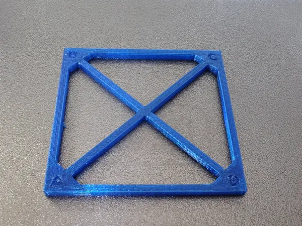
The test frame is 68 × 68 mm, its diagonal measures 96.2 mm – that fits into an ordinary 150 mm caliper. It also has a diagonal cross of two 3 mm wide struts so the thin frame does not get squeezed under the caliper jaws. The struts end on the inside of the corners, leaving the outer corners free as measuring points. The corners carry engraved letters in exactly the arrangement used in Klipper's documentation: A front left, AD along X.
The resolution is sufficient: with a 68 mm edge, every tenth of a degree of skew produces about 0.17 mm difference between the diagonals – far above what a caliper resolves.
Is the skew stable?
The first result: AC 95.15 mm, BD 94.65 mm. Half a millimetre difference, that is 0.30 degrees. Over the roughly 400 mm length of the gantry, the right end therefore sits a good two millimetres further back than the left.
Before compensating something like this in software, one question has to be answered. With only one switch, nothing holds the gantry in position once the motors are de-energised – at the end of a print, after the idle timeout, after every restart. The gantry then settles where the forces of the two belts balance. If it ends up in the same place every time, the skew is a property of the machine. If it ends up anywhere, every correction will be wrong on the next print.
The test: motors de-energised, gantry pushed back and forth by hand several times, released, printed again.
| AC | BD | AC − BD | Angle | |
|---|---|---|---|---|
| 1 · no compensation | 95.15 | 94.65 | 0.50 | 0.30° |
| 2 · gantry moved freely in between | 95.30 | 94.80 | 0.50 | 0.30° |
| 3 · with compensation | 95.15 | 95.15 | 0.00 | 0.00° |
The first two prints differ by 0.15 mm in absolute value – that is print and measurement scatter. The difference is identical to the hundredth. The gantry reliably returns to the same position, and only that justifies a software correction.
Ad · Affiliate link – if you buy through it, I may earn a commission. It doesn’t change the price for you.

Compensation in Klipper
Klipper ships [skew_correction] for this. It takes three measurements – both diagonals and side AD – and computes a shear factor from them. The excerpt from the Klipper source:
# klippy/extras/skew_correction.py
def calc_skew_factor(ac, bd, ad):
    side = math.sqrt(2*ac*ac + 2*bd*bd - 4*ad*ad) / 2.
    return math.tan(math.pi/2 - math.acos(
        (ac*ac - side*side - ad*ad) / (2*side*ad)))
The expression inside acos is the law of cosines in triangle ACD, i.e. the cosine of the angle at A. The result is the cotangent of that angle. A look at the source pays off in one place: the sign depends solely on which corner is called A. Because the frame carries the letters exactly like Klipper's sketch, it comes out right without thinking.
One detail does not seem to fit the explanation above at first: it is the gantry that is skewed, i.e. the X direction – yet Klipper corrects X as a function of Y (x' = x − y · factor) and leaves Y alone. For the shape of the part this makes no difference. Both shears turn the parallelogram back into a rectangle; they only differ in how the finished part as a whole lies on the bed – here rotated by the 0.30 degrees the gantry is skewed. A part that lies on the bed rotated by three tenths of a degree is dimensionally accurate; one with 89.7-degree corners is not.
SET_SKEW XY=95.225,94.725,67.6     # Mittel aus beiden Drucken
GET_CURRENT_SKEW
// XY Skew: 0.005265 radians, 0.30 degrees
SKEW_PROFILE SAVE=hevort
SAVE_CONFIG
More important than the factor is when it applies. Klipper recommends loading the compensation only after all moves at the edge of the build volume. Here that is no formality: the purge line runs at X 0 from Y 10 to Y 100. With the compensation loaded, Klipper would shift it up to half a millimetre to the left – past the endstop.
[gcode_macro START_PRINT]
SET_SKEW CLEAR=1                ; Homen, Z-Tilt, Mesh, Purge ohne Ausgleich
G28
; ... Z_TILT_SICHER, BED_MESH_CALIBRATE, Purge-Linie bei X0 ...
SKEW_PROFILE LOAD=hevort        ; erst nach der Purge-Linie

[gcode_macro END_PRINT]
SET_SKEW CLEAR=1
G1 X200 Y395 F5000The compensation shifts X proportionally to Y. At Y 400 that is 2.1 mm. A part at the very rear left edge can therefore end up beyond X 0, and Klipper aborts with “Move out of range”.
The verification print ran with the profile loaded: both diagonals 95.15 mm. SKEW_PROFILE LOAD reports nothing, and END_PRINT resets the compensation at the end – so the only proof that it worked is the part itself. But that is enough.
What I got wrong
I almost corrected without a stability test
A single print with 0.50 mm diagonal difference looks like a clear case. Without a second print after moving the gantry freely, it would have remained open whether the correction still holds after the next power-up. Only that print – exactly the same difference – justified the software compensation.
Printer: HevORT CoreXY with four XY motors, Klipper v0.13.0-743, BTT Eddy, Phaetus Rapido 2, 0.4 mm nozzle, PETG. Slicer: OrcaSlicer 2.4.2. Test frame parametric in OpenSCAD.
All numbers come from measurements on this machine – caliper, Moonraker API, Klipper output. They apply to this printer, not in general.
Where things stand
| What | before | after | Why |
|---|---|---|---|
| Y1 motor, bearing cap | preloaded, motor loose | remounted | friction grows with speed |
| Y endstops | 2 (PG10, PG11) | 1 (PG10) | no fighting |
| Homing y − y1 | 3–18 mm | 0 steps | measured, three times |
| XY skew | 0.30° | 0.00° | skew_correction, profile hevort |
| max_velocity | 300 mm/s | 300 mm/s | stays until the warm test |
In the long run the second endstop could come back – mechanically adjusted so that it triggers at the same time as the first one when the gantry is square. Then homing would actually square the gantry, and the software correction would be unnecessary.
Ad · Affiliate link – if you buy through it, I may earn a commission. It doesn’t change the price for you.