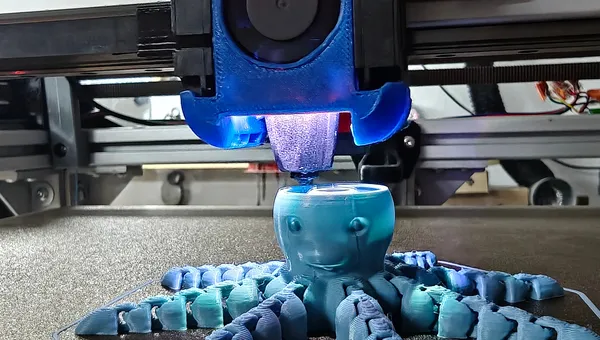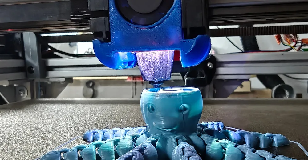
The model is a chain octopus: eight arms of ten links each, all movable, all printed in one piece. Each link hangs on a cross pin, and between link and pin there is a designed clearance of 0.305 mm. Eighty of these clearances, and not one of them may fuse.
This is the insight that turned the whole approach around: the printed gap is always exactly one layer high – provided a slice plane lands inside the clearance at all. If none does, there is no gap, and the joint is solid.
Thinner layers make the joints tighter, not safer. The only thing that counts is that each of the eighty clearances is hit by at least one slice plane – and that depends on layer height and first layer together, because the first layer shifts the phase of the entire grid.
The wrong criterion and its correction
My first criterion was wrong: I required a whole layer band to fit inside the clearance, and concluded that at 0.34 mm all eighty joints would fuse. The printer said otherwise – a print at 0.34 moved freely. The criterion was too strict: it's enough for the plane to lie inside the clearance.
# tools/gapcheck.py — the correct criterion
def resolved(a, b, h, first):
    """the best-placed slice plane in (a, b)"""
    best = None
    cand = [first / 2.0]
    n = 2
    while True:
        z = first + (n - 1.5) * h
        if z >= b:
            break
        cand.append(z)
        n += 1
    for z in cand:
        if a < z < b:
            c = (z - a, b - z)
            if best is None or min(c) > min(best):
                best = c
    return best
That turns a guess into a check. The script runs all 80 joint clearances on the forty cross pins through every combination of layer height and first layer. Each table cell contains two values:
- first: how many of the 80 clearances are not hit by any slice plane – those joints fuse. A 0 means: all of them move.
- second: the smallest margin in mm – how close the tightest slice plane sits to the edge of its clearance. The larger it is, the more tolerance is left for printer inaccuracies.
| Layer height | 1st layer 0.22 | 0.26 | 0.28 | 0.30 | 0.32 |
|---|---|---|---|---|---|
| 0.28 mm | 0 · 0.034 | 0 · 0.018 | 0 · 0.014 | 0 · 0.031 | 0 · 0.027 |
| 0.30 mm | 0 · 0.003 | 0 · 0.008 | 0 · 0.028 | 0 · 0.010 | 0 · 0.010 |
| 0.32 mm | 6 fused | 0 · 0.014 | 6 fused | 0 · 0.011 | 0 · 0.031 |
0.32 mm is the fastest usable layer height – but only with a matching first layer. With 0.22 or 0.28, six cross pins fall exactly between two planes and turn solid. The 0.32 / 0.32 combination has the same 0.031 mm margin as the previous 0.28 / 0.22 setup – with 14 % fewer layers.
Why a brim is not an option
The obvious reflex for adhesion problems is a brim. On the chain octopus it's ruled out, and the reason can be put in numbers: between two consecutive links of the same arm there are 1.01 mm on the bed. Across forty such pairs.
A brim would bridge those forty gaps – gluing together exactly the joints that are supposed to move. It would improve adhesion and ruin the object at the same time. Between neighbouring arms, by contrast, there are 6.11 mm; a brim would be harmless there, but it wouldn't help there either.
Mouse ears or other sacrificial pads were also out – the model should come off the bed without post-processing. That left only one option: enlarging the contact area of the links themselves.
Ad · Affiliate link – if you buy through it, I may earn a commission. It doesn’t change the price for you.

The barrel becomes a tent
Every chain link is a barrel lying on its side. A lying barrel touches the bed along a narrow strip – on the weakest link that was 17.5 mm² at 3.9 mm width. Too little for a part that grows forty millimetres tall above it.
The first reflex, flattening the underside further, ran out quickly: the bed_flat parameter can be raised from 0.80 to at most 0.92 (+6 % width); beyond that, the flat cuts into the ring under the bore – and that ring carries the arm.
The solution was to stretch the cross-section in y instead of flattening it in z: wide at the bottom, straight flanks slanting upwards, still round on top. A tent instead of a barrel.
// The sole the barrel gets hulled onto. Its outline is the barrel's
// OWN bed contact, widened in y – so it ends exactly where the
// barrel leaves the bed. The contact area gets wider without
// growing a single millimetre longer. That is precisely what
// protects the 1.01 mm to the next link.
function foot_half(d, u, s) =
    let (zax = d/2 - bed_flat, r = barrel_r(d, u))
    r > zax ? s*sqrt(r*r - zax*zax) : 0;

module barrel(len, d) {
    // ...
    if (arm_spread <= 1 + eps) core();
    else hull() { core(); barrel_sole(len, d, arm_spread); }
}
Weakest link, arm_spread 1.00 → 1.80:
| Metric | before | after | Factor |
|---|---|---|---|
| Contact area | 17.5 mm² | 35.1 mm² | 2.00× |
| Contact width | 3.9 mm | 8.2 mm | 2.10× |
| Gap within the same arm | 1.01 mm | 1.01 mm | unchanged |
| Gap to neighbouring arm | 6.11 mm | 6.11 mm | unchanged |
Because the stretch only happens in y, the barrel dips below the bed at exactly the same x – the area gets wider, never longer. The critical 1.01 mm stay untouched. As a side effect, an overhang disappears: the lower flank of a lying barrel grows outwards as it rises; stretched, it leans inwards.
Tipping resistance scales with the square of the contact width. So 2.1× the width gives roughly 4.4× the resistance to tipping over.
On the first attempt I required a whole layer band inside the joint clearance instead of just the slice plane. The result was a clean, convincing, wrong table – disproved by an octopus I had already printed and that moved just fine.
The maths was correct. Only the assumption underneath was wrong – and a clean table doesn't show you that.
Model: parametric chain octopus in OpenSCAD, check tools in Python. Printer: HevORT, Klipper v0.13.0-743, 0.4 mm nozzle. Slicer: OrcaSlicer 2.4.2.
Verified model figures: volume 29.6 cm³, total bed contact 2262 mm², smallest single contact 35.1 mm², joint clearance 0.305 mm, thinnest wall 1.39 mm, overhang share 11.1 %.
This series
One evening of troubleshooting a chain octopus produced four topics that can each be read on their own:
- Klipper Bed Mesh: A Missing Zero Reference Costs 0.14 mm
- Print-in-Place: Layer Height Decides Whether Joints Move – this article
- OrcaSlicer & Klipper: 34 % less print time (coming soon)
- Seven fallacies in Klipper troubleshooting (coming soon)
Ad · Affiliate link – if you buy through it, I may earn a commission. It doesn’t change the price for you.