Why CAD with AI?
I'm skeptical when it comes to „AI does CAD now" – CAD lives on precise dimensions, not word clouds. But the Robust MCP Bridge setup connects FreeCAD directly to Claude Code via the Model Context Protocol. That lets the AI not just talk about geometry but actually build it: create bodies, draw sketches, cut booleans, export. I installed it and tested it on a concrete job – including a printable screw with a matching nut.
The architecture: two components
The setup has two parts you mustn't mix up:
- MCP server (
freecad-robust-mcpfrom PyPI) – the bridge between Claude and FreeCAD. Runs as its own process. - Workbench/add-on („Robust MCP Bridge") – runs inside FreeCAD and exposes the connection via XML-RPC on port
9875.
So Claude talks to the MCP server, the MCP server talks to the workbench via XML-RPC, and the workbench drives FreeCAD. Sounds like a lot of chain – but that separation is exactly what makes it stable.
Installation on Linux
I installed the MCP server with pipx under Python 3.11. The version isn't optional: FreeCAD's ABI requires it, and with 3.12+ it breaks. Then register it with the Claude CLI – user scope, XML-RPC mode:
# MCP server via pipx under Python 3.11 (ABI compatibility with FreeCAD)
pipx install --python python3.11 freecad-robust-mcp

# Register with the Claude CLI (user scope, XML-RPC mode)
claude mcp add freecad --scope user --env FREECAD_MODE=xmlrpc
Important: MCP servers are only loaded at Claude Code startup. After registering, a restart was needed, otherwise the freecad tool won't show up.
Three pitfalls – and the fixes
Before the connection worked, three typical traps were in the way – none of them the AI part, all FreeCAD quirks:
- „Failed to connect": server 0.6.1 opens a connection to FreeCAD immediately on startup – but it wasn't running yet. Fix: reverse the order, start the bridge in FreeCAD first, then Claude/the server.
- Add-on not in the Addon Manager: not (yet) listed in the official catalog. Fix: clone the repo manually into the Mod folder with
git clone. - Workbench still doesn't appear: FreeCAD 1.1 uses a versioned data directory –
…/data/FreeCAD/v1-1/Mod/instead of the old…/data/FreeCAD/Mod/. Fix: move the add-on into the correct, versioned folder.
Debugging ran fully headless: I started FreeCAD with QT_QPA_PLATFORM=offscreen and queried FreeCADGui.listWorkbenches() via a diagnostic script until the FreecadRobustMCPBridgeWorkbench appeared in the list.
# Diagnostic: start FreeCAD headless and list workbenches
QT_QPA_PLATFORM=offscreen freecadcmd -c \
  "import FreeCADGui; print(list(FreeCADGui.listWorkbenches()))"

# Fetch the add-on manually and place it in FreeCAD 1.1's VERSIONED Mod directory
git clone https://github.com/spkane/freecad-addon-robust-mcp-server
# -> move to …/data/FreeCAD/v1-1/Mod/ (not …/data/FreeCAD/Mod/)
Connected: 150+ tools
After that the server reported connected: true, mode xmlrpc, FreeCAD 1.1.1 – and Claude had access to over 150 tools: primitives, PartDesign, boolean operations, the sketcher, export and even direct Python execution inside FreeCAD. This is where it gets interesting.
What Claude actually built
No toy cube – three real parts, each with a different challenge:
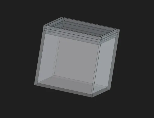
1. Parametric click-box
A small container with a snap lid. The trick: all dimensions hang off a Param spreadsheet – real FreeCAD parametrics. The snap mechanism is a circumferential groove in the inner wall plus a catch bead on a springy lid skirt (0.2 mm clearance, 0.7 mm engagement), built from primitives and boolean operations (Box / Cut / Fuse).
To see how well the parametrics really hold up, I tried it right away: originally built as 20×20×40 mm, then changed in the Param spreadsheet to 40×40×40 mm – one value adjusted, recompute, and the box and lid scale along cleanly. That's exactly what you build parametrically for.
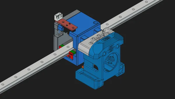
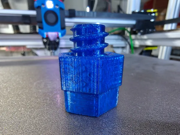
2. Screw + nut with a real thread
Now it gets serious: a real thread via Part.makeHelix plus a profile sweep (makePipeShell along the helix) – the only clean way to get thread flanks, impossible with pure primitives. Trapezoidal thread, Ø20 mm, 5 mm pitch, 6 turns; hex head and nut via boolean cut. And the key thing for 3D printing: screwable thanks to clearance – the nut thread was enlarged 0.4 mm radially versus the screw thread to keep it FDM-friendly.
3. Refinements on request
Touch-ups happened in dialogue: a 45° lead-in chamfer at the screw tip plus a countersink on both sides, plus a 0.5 mm chamfer on all hex edges (top, bottom, corners). Exactly the little details that make a printed part actually usable.
Method: two CAD paradigms
What was interesting is that Claude deliberately mixed two modelling approaches: primitives + boolean (robust for rectangular parts like the box) and helix + sweep/extrusion (needed for threads). The third classic route – sketch + extrusion via PartDesign – was on the table but wasn't needed here. So the AI picks the paradigm to suit the geometry instead of forcing everything into one scheme.
By the way, the whole stack runs headless on a small, power-sipping Linux mini-PC in my homelab – FreeCAD in offscreen mode, Claude Code alongside. For exactly these always-on workloads I use a Beelink:
Ad · Affiliate link – if you buy through it, I may earn a commission. It doesn’t change the price for you.

Workflow & verification
Every step ran verified rather than blind: after building, Shape.isValid() and a solid check, then a screenshot via saveImage() for visual control. The add-on's built-in screenshot tool had a bug – worked around via the direct FreeCAD call. Finally exported as print-ready .stl and stored in ~/3D_Printing/:
ClickBox.FCStd
ClickBox_Body.stl
ClickBox_Lid.stl
ScrewNut.FCStd
Screw_M20coarse.stl
Nut_M20coarse.stl
The FreeCAD source files to inspect, adapt and print yourself – the box's Param spreadsheet can be edited directly:
ClickBox.FCStd
FreeCAD source file of the parametric click-box (incl. Param spreadsheet).
ScrewNut.FCStd
FreeCAD source file of the screw + nut (trapezoidal thread via helix sweep).
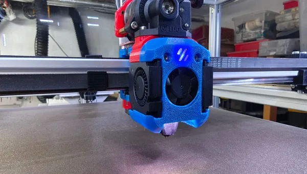
Print test: does the nut fit?
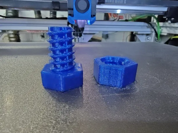
And the moment of truth: the nut threads onto the screw really nicely – great fit, neither too tight nor too loose. The 0.4 mm of radial clearance on the thread was spot on for FDM.
An honest blemish: the nut's hex (32 mm across flats) is a bit wider than the screw's (30 mm). The reason is instructive – I hadn't specified any dimensions for the wrench sizes, so the AI chose two slightly different ones. That's exactly the lesson: the AI builds precisely, but only what you specify. Had I caught it before printing, a single extra prompt would have matched the two wrench sizes in no time.
Lessons Learned & Conclusion
Honestly surprised: it worked remarkably well. What's notable is where the friction was – not in the AI part, but in FreeCAD quirks (connection order, the versioned Mod directory, the screenshot bug). Once you understand those, the AI models with surprising precision, including clean threads and print-ready tolerances.
A few caveats remain: embedded mode crashes on macOS/Windows (library linking), XML-RPC is the stable route; screenshots only work in GUI mode. For Linux users, though, that's no dealbreaker.
Bottom line: a surprisingly usable workflow. The AI takes over the tedious geometry clicking; the human supplies dimensions, tolerances and the final word – like the hex above. For quick, parametric parts straight out of a conversation, this is now a permanent part of my workshop.
Ad · Affiliate link – if you buy through it, I may earn a commission. It doesn’t change the price for you.