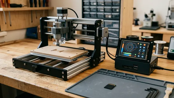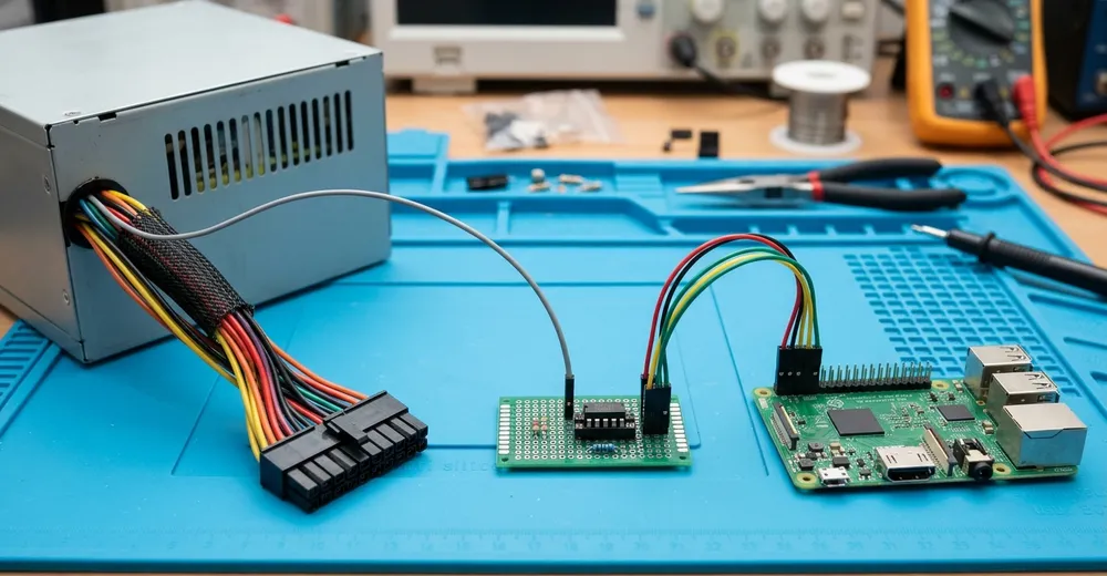
The mill is driven by an Arduino Uno with a CNC shield running Grbl 1.1h, with a Raspberry Pi 3 running CNCjs in front of it. The Pi does only one thing on the electrical side: it switches the power supplies on and off. For the stepper motors that's a converted ATX power supply from an old PC, switched via its PS_ON line.
After rebuilding the Pi (the whole story is in the article about the SD card failure), homing failed. Grbl raised an alarm at MPos Z 67.501 – exactly 1.5 times the configured travel distance $132=45. So Grbl had counted off the full search distance, but nothing had actually moved. The motors had no power.
The switching script told me why, I just didn't understand it at first: “GPIO26 does not take level 'lo' – line is stuck.” And every now and then the drives switched on by themselves when someone bumped into the machine.
What PS_ON actually is
Besides the supply rails, an ATX power supply has two signal lines that matter here:
- PS_ON – the power-on line, active low. Inside the power supply it is pulled up to the 5 V standby rail through a resistor. Pull it to ground and the power supply starts up.
- PWR_OK – the power supply's signal that all voltages are stable.
The first point is the crucial one: when the supply is off, PS_ON sits at around 5 V. The Raspberry Pi's GPIOs work at 3.3 V – and are not 5 V tolerant.
According to the ATX standard, PS_ON is green and PWR_OK is grey. On my converted power supply, the power-on wire was grey. If you go by colour alone, you'll mix the two up.
A reliable way to tell them apart with the power supply switched off (mains plug in, standby running): PS_ON sits at about 5 V, PWR_OK at ground. Measure DC voltage – an AC measurement only shows the residual ripple. That's exactly why my first measurement gave a meaningless 200 mV.
Why this destroys the GPIO
The old installation had been running since 2023 (according to the backups) with PS_ON wired directly to GPIO26, entered in Klipper/Moonraker as pin: !gpio26. Presumably the 5 V pushes current through the pull-up in the power supply and the GPIO's protection diode into the Pi's 3.3 V rail. The resistor in the power supply limits that current, which is why the pin doesn't die immediately – just eventually. I haven't measured this mechanism; all I know for sure is that PS_ON on a 3.3 V GPIO held the pin permanently high and destroyed it, and the later attempts to drive it probably made things worse.
The picture at the end: GPIO26 sits hard at high and doesn't follow the pull-down – even with the cable unplugged. Three comparison pins followed cleanly. The pin is dead.
The occasional self-switching on vibration, by the way, had a more harmless cause: the Dupont connector on the wire was loose. A brief contact to ground is all it takes for the power supply to start.
Troubleshooting: measure passively first
The GPIO assignments were lost along with the SD card. Driving a pin as an output without knowing what's connected to it is not a good idea on a machine with an emergency stop and power supplies. The alternative is a passive measurement: configure each pin as an input, once with the internal pull-up and once with the pull-down. A free pin follows the resistor. A pin that something external is pulling on does not.
#!/bin/bash
# Welche GPIOs sind von außen beschaltet? Rein passiv, es wird kein Ausgang getrieben.
# Pins als Argumente, z. B. ./pins.sh 5 6 12 13 16 19 20 21 26
# Achtung: Pins bleiben danach als Eingang mit Pull-down stehen.
for p in "$@"; do
  pinctrl set "$p" ip pu; sleep 0.05
  a=$(pinctrl get "$p" | grep -oE '\| (hi|lo)' | cut -c3-)
  pinctrl set "$p" ip pd; sleep 0.05
  b=$(pinctrl get "$p" | grep -oE '\| (hi|lo)' | cut -c3-)
  case "$a/$b" in
    hi/lo) echo "GPIO$p: frei" ;;
    hi/hi) echo "GPIO$p: von außen HOCH gehalten" ;;
    lo/lo) echo "GPIO$p: von außen nach MASSE gezogen" ;;
    *)     echo "GPIO$p: unklar ($a/$b)" ;;
  esac
done
I measured all the freely available GPIOs. Result: GPIO16 and GPIO26 held high externally, GPIO20 and GPIO21 pulled to ground, twelve more pins free. What that meant only became clear from two old backups from 2023 – a moonraker.conf and an OctoPrint backup:
| Pin | Measurement | According to backup | Meaning |
|---|---|---|---|
| GPIO26 | hi/hi | pin: !gpio26 | Drives, active low – PS_ON |
| GPIO20 | lo/lo | pin: gpio20 | Spindle relay, active high |
| GPIO16 | hi/hi | physicalbutton, Normally Closed | E-stop NC contact to 3.3 V |
| GPIO21 | lo/lo | – | unknown |
Before looking at the backups, GPIO16 was the most promising candidate for the power supply – Claude suggested driving it low as an output. But GPIO16 had a closed emergency-stop switch wired to 3.3 V. That would have become a short circuit straight across the output driver. The only thing that prevented it was asking before driving the pin.
The proof that the grey wire itself supplies voltage came from a swap test: wire moved from GPIO26 to the free GPIO19 – and GPIO19 jumped from hi/lo (free) to hi/hi. With the wire unplugged, GPIO26 still stayed at hi/hi. Only this second measurement proves the defect. “Holds high” just means “holds high” as long as a cable is still plugged in.
The fix: a PC817 in between
An optocoupler galvanically isolates the two sides. The Pi only drives an LED; on the power supply side, a phototransistor pulls PS_ON to the power supply's ground. The power supply's 5 V never reaches the Pi again.
| PC817 pin | Function | Connection |
|---|---|---|
| 1 | Anode (LED) | GPIO19 via 330 Ω |
| 2 | Cathode (LED) | Pi ground |
| 4 | Collector | PS_ON (in my case: the grey wire) |
| 3 | Emitter | Power supply ground (black, COM) |
With 330 Ω, about (3.3 V − 1.2 V) / 330 Ω ≈ 6 mA flows through the LED. That is below what a GPIO is allowed to supply, and enough for the transistor to reliably pull the small current of the pull-up in the power supply to ground.
Two side effects make this circuit nicer than the original:
- Active-high logic. GPIO high → LED on → transistor conducts → PS_ON to ground → power supply on. It reads the way you'd expect.
- Off is the resting state. Without LED current the transistor is open and the power supply stays off – even while the Pi is booting and the GPIOs are floating.
To make sure the pin is at a defined low after booting, add a line to config.txt:
# /boot/firmware/config.txt
# Antriebe beim Booten aus (PC817 an GPIO19, aktiv high)
gpio=19=op,dl- No comment at the end of a line. gpio=19=op,dl # Antriebe is ignored completely. Put comments on their own lines only.
- Lines are truncated after 98 characters – without warning. It happened to me with long dtoverlay= lines for the touch display; the details are in the rebuild article.
A switching script with a pre-check
The first version of the switching script drove the pin for 50 ms and checked afterwards whether the level had arrived. Against a line that is held at 5 V externally, that is exactly backwards – it probably finished off GPIO26.
The new version checks beforehand: the pin first becomes an input with a pull resistor in the target direction. If it doesn't follow, something external is holding against it, and the script doesn't drive at all.
#!/bin/bash
# Antriebs-Netzteil über PC817 an GPIO19 schalten (aktiv high)
set -eu
PIN=19

setze_gesichert() {   # $1 = hi | lo
  local ziel=$1 pull
  [[ $ziel == hi ]] && pull=pu || pull=pd
  pinctrl set "$PIN" ip "$pull"
  sleep 0.05
  if ! pinctrl get "$PIN" | grep -q "| $ziel"; then
    echo "GPIO$PIN folgt dem Pull nicht – Fremdbeschaltung, treibe nicht." >&2
    [[ ${ERZWINGEN:-0} == 1 ]] || exit 1
  fi
  pinctrl set "$PIN" op "d${ziel:0:1}"   # dh oder dl
}

case "${1:-status}" in
  ein)    setze_gesichert hi; echo "Antriebe: ein" ;;
  aus)    setze_gesichert lo; echo "Antriebe: aus" ;;
  status) pinctrl get "$PIN" ;;
  *)      echo "Aufruf: $0 {ein|aus|status}" >&2; exit 2 ;;
esac
In CNCjs the script is registered as a Command, so the power supplies can be switched straight from the UI. One small stumbling block: editing ~/.cncrc by hand isn't enough, because CNCjs keeps its configuration in memory. Create new commands via the UI or POST /api/commands.
The test on 22 September: antriebe ein → “Antriebe: ein”, pinctrl shows 19: op | hi, and the power supply starts up. After that, homing ran through again.
What I'm taking away
- Never connect foreign control lines directly to a GPIO. If you can't be sure the line carries at most 3.3 V, put an optocoupler in between. It costs one component and one resistor.
- Measure passively first, then drive. The pull-up/pull-down method answered every question without risking anything.
- Old backups are worth their weight in gold. Without the 2023 configuration files, the pin assignment could only have been reconstructed by guessing – with an emergency-stop contact right in the middle.
- Individual Dupont connectors don't hold up in a vibrating machine. The PS_ON wire will be re-crimped, and all control lines get a shared connector housing with strain relief.
Hardware: Raspberry Pi 3B, Arduino Uno with CNC shield (Grbl 1.1h), converted ATX power supply for the stepper motors, PC817 with 330 Ω. GPIO access via pinctrl.
This article only concerns the low-voltage side at the ATX connector. Modifying the power supply itself is not covered – there is mains voltage inside, so the case stays closed.
Still open is the Pi's own power supply: it's marginal, and I suspect it's behind the occasional USB dropouts to the Arduino. A beefier power supply for the Pi and a separate supply for the Arduino are planned.
Ad · Affiliate link – if you buy through it, I may earn a commission. It doesn’t change the price for you.