Why a complete firmware update is necessary
Klipper consists of several components: the host software on the Raspberry Pi and the firmware on every connected MCU. During an update, all MCUs must receive the exact same firmware version. If the versions don't match, Klipper refuses to start with a dreaded “Protocol Error”.
This guide shows the complete process using a typical setup as an example:
- Mainboard: BTT Octopus Pro (STM32F429) via USB
- Probe: BTT Eddy USB (RP2040) via USB
- Toolboard: EBB / SB2209 or similar (STM32G0B1) via CAN bus
- Host MCU: Raspberry Pi (Linux process)
If your setup uses different hardware, adjust the processor and interface settings accordingly – the basic structure stays the same.
Step 1: Update the host system (Raspberry Pi)
Before flashing any hardware, the Klipper software on the Pi must be up to date. Always update the host first, then the MCUs.
1.1 Apply the Klipper update
cd ~/klipper
git pull
sudo service klipper restart
1.2 Flash the Linux MCU ([mcu rpi])
Many setups use the Pi itself as an MCU – e.g. for ADXL345 accelerometers or GPIO control. This MCU also has to be recompiled, otherwise you'll hit the Protocol Error.
cd ~/klipper
make menuconfig
menuconfig setting:
- Micro-controller Architecture: Linux process
That's the only option – there are no further sub-menus. Confirm and save.
make clean && make
make flash
The Pi flashes itself. No reboot needed, Klipper will load the new version automatically.
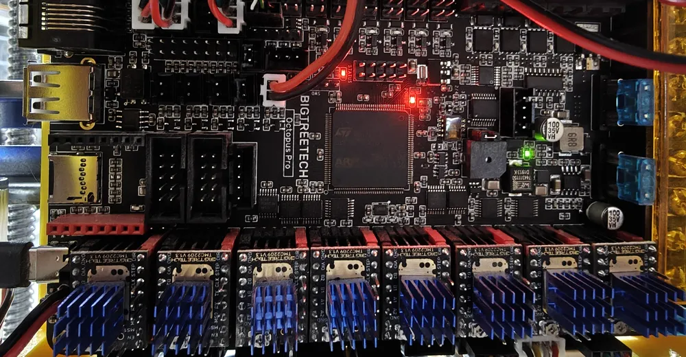
Step 2: Flash the mainboard (BTT Octopus Pro – STM32F429)
The Octopus Pro is connected to the Pi via USB. It uses an STM32F429 chip with a 32 KiB bootloader.
Ad · Affiliate link – if you buy through it, I may earn a commission. It doesn’t change the price for you.

2.1 Configure menuconfig
cd ~/klipper
make menuconfig
menuconfig settings in detail:
- Micro-controller Architecture: STMicroelectronics STM32 – the STM32 family from ST
- Processor model: STM32F429 – the chip on the Octopus Pro. On the Octopus V1.1 it would be e.g. STM32F446
- Bootloader offset: 32KiB bootloader – the Octopus Pro has a 32 KiB bootloader. Wrong offset = board won't boot!
- Clock Reference: 8 MHz crystal – external crystal on the board. Some boards use 12 MHz – check the board documentation
- Communication interface: USB (on PA11/PA12) – the USB pins of the Octopus Pro. Other boards may use different pins (e.g. PA9/PA10)
The bootloader occupies the first bytes of the flash memory. Klipper needs to know at which address the actual firmware begins. A wrong offset overwrites the bootloader and the board no longer starts (recovery then only via DFU or ST-Link).
2.2 Compile and flash (SD card method)
make clean && makeThe finished firmware is located at out/klipper.bin.
Flashing procedure:
- Copy
out/klipper.binfrom the Pi to your PC (e.g. via SCP/SFTP). - Rename the file to firmware.bin – the name matters!
- Copy it onto a FAT32-formatted SD card (max. 32 GB recommended).
- Insert the SD card into the slot on the Octopus.
- Press the reset button on the board (or briefly cut the power).
- Wait about 5 seconds, then check the SD card.
The file on the SD card is now named FIRMWARE.CUR instead of firmware.bin. That confirms the bootloader has flashed the firmware.
Alternatively you can flash directly via USB if you know the serial ID:
make flash FLASH_DEVICE=/dev/serial/by-id/usb-Klipper_stm32f429xx_...The SD method is, however, the most reliable and also works with corrupted firmware.
Step 3: Flash the probe (BTT Eddy USB – RP2040)
The BTT Eddy is an inductive probe with its own RP2040 chip and a permanent USB connection. It too needs the matching Klipper firmware.
Ad · Affiliate link – if you buy through it, I may earn a commission. It doesn’t change the price for you.

3.1 Configure menuconfig
cd ~/klipper
make menuconfig
menuconfig settings in detail:
- Micro-controller Architecture: Raspberry Pi RP2040 – the chip in the Eddy (and many other boards like the Pi Pico)
- Bootloader: No bootloader – the RP2040 has no permanent bootloader in the classic sense, it is flashed in UF2 boot mode
- Flash chip: W25Q080 with generic 03h SPI – standard flash chip on the Eddy
- Communication interface: USB – the Eddy is permanently attached via USB to the Pi
On the RP2040 the firmware is written directly into the flash. The chip's boot ROM takes over the bootloader function – you just have to activate boot mode manually.
3.2 Compile and flash
make clean && makeActivate boot mode:
- Disconnect the USB cable from the Eddy (or unplug it at the Pi).
- Hold down the boot button on the Eddy.
- Plug the USB cable back in (keep holding the button).
- Release the button – the Eddy now shows up as a USB bootloader device.
make flash FLASH_DEVICE=2e8a:0003The ID 2e8a:0003 is the USB ID of the RP2040 in boot mode. If unsure:
lsusb | grep -i "2e8a"After flashing, the Eddy restarts automatically with the new firmware.
Step 4: Flash the toolboard (STM32G0B1 via CAN bus)
The toolboard (e.g. BTT EBB36/42, SB2209, Mellow FLY-SB2040) is attached to the CAN bus. Here the CAN bitrate must match exactly.
4.1 Configure menuconfig
cd ~/klipper
make menuconfig
menuconfig settings in detail:
- Micro-controller Architecture: STMicroelectronics STM32
- Processor model: STM32G0B1 – the chip on the toolboard. Older versions may use STM32F072
- Bootloader offset: No bootloader – Klipper is flashed directly. If Katapult is installed: 8KiB bootloader
- Clock Reference: 8 MHz crystal – standard on most STM32 toolboards
- Communication interface: CAN bus (on PB0/PB1) – the CAN pins of the toolboard. Always check the schematic – wrong pins = no communication
- CAN bus speed: 1000000 – must be identical on all CAN participants! Common values: 250000, 500000, 1000000
CAN pins on common boards: BTT EBB36/42 v1.2 & SB2209 = PB0/PB1; the Mellow FLY-SB2040 uses an RP2040 with its own CAN configuration. Always check the pin assignment of the specific board revision. All devices on the CAN bus must use the same bitrate (toolboard, can0 on the Pi, and a CAN bridge if present). Typically 500000 or 1000000.
4.2 Compile and flash
make clean && makeRecommended: flash via USB (rescue path). Flashing over CAN doesn't always work reliably – especially without a Katapult bootloader. So connect the toolboard once via USB directly to the Pi:
- Disconnect the CAN cable from the toolboard.
- Connect a USB cable between toolboard and Pi.
- Determine the serial ID:
ls /dev/serial/by-id/*Example output:
/dev/serial/by-id/usb-Klipper_stm32g0b1xx_12345678-if00Flash, then disconnect USB and reconnect the CAN cable:
make flash FLASH_DEVICE=/dev/serial/by-id/usb-Klipper_stm32g0b1xx_YOUR_IDAlternatively: flash over CAN (with the Katapult/CanBoot bootloader). If Katapult is installed on the toolboard, you can flash directly over the CAN bus:
python3 ~/katapult/scripts/flash_can.py -i can0 -u YOUR_CAN_UUID -f ~/klipper/out/klipper.binYou can find the CAN UUID with:
~/klippy-env/bin/python ~/klipper/scripts/canbus_query.py can0Summary: example setup
| Component | Chip | Connection | Identification |
|---|---|---|---|
| BTT Octopus Pro | STM32F429 | USB | /dev/serial/by-id/usb-Klipper_stm32f429xx_… |
| BTT Eddy USB | RP2040 | USB | /dev/serial/by-id/usb-Klipper_rp2040_… |
| Toolboard (EBB/SB) | STM32G0B1 | CAN (1M) | UUID (e.g. 5e654f097xxx) |
| Raspberry Pi | Linux | Internal | n/a |
Checklist after flashing
1. Start the Klipper service
sudo service klipper start2. Check the firmware versions
Open Mainsail or Fluidd → Machine → System Information. All MCUs must show the identical version string, e.g.:
mcu: Klipper v0.13.0-xxx
mcu rpi: Klipper v0.13.0-xxx
mcu EBBCan: Klipper v0.13.0-xxx
mcu eddy: Klipper v0.13.0-xxx
If one version differs, that MCU was not flashed correctly.
3. Check the CAN interface
ip -details link show can0Expected output (truncated):
can0: <NOARP,UP,LOWER_UP,ECHO> mtu 16 qdisc pfifo_fast state UP
    ... bitrate 1000000 sample-point 0.750
If can0 is not up, check /etc/network/interfaces.d/can0:
allow-hotplug can0
iface can0 can static
    bitrate 1000000
    up ifconfig $IFACE txqueuelen 1024
Adjust the bitrate to your setup and restart the interface:
sudo ifdown can0 && sudo ifup can04. Homing test
Run G28 (Home All) – keep a finger on the emergency stop! This checks whether endstops and probe work correctly.
5. Probe calibration
After a firmware update, offsets can change slightly. Run the calibration again:
PROBE_CALIBRATE
BED_MESH_CALIBRATE
Troubleshooting
| Problem | Cause | Solution |
|---|---|---|
| “Protocol Error” after update | Firmware versions don't match | Flash all MCUs to the identical version |
| CAN toolboard doesn't respond | Bitrate wrong or interface down | Check ip link show can0, compare bitrate |
| SD card: file stays firmware.bin | Board didn't flash | Try another SD card, format FAT32, press reset again |
| make flash on the RP2040 fails | Boot mode not active | Hold the button while plugging in, check lsusb |
| Toolboard via USB: “No device found” | Wrong device path | Re-check ls /dev/serial/by-id/*, test the USB cable |
| Eddy reports wrong values | Calibration missing | Re-run PROBE_CALIBRATE and the Eddy calibration |
menuconfig quick reference
For a quick overview – all four configurations at a glance:
# Pi (Linux MCU)
[*] Linux process

# Octopus Pro (STM32F429)
[*] STMicroelectronics STM32
Processor: STM32F429
Bootloader: 32KiB bootloader
Clock: 8 MHz crystal
Interface: USB (on PA11/PA12)

# Eddy USB (RP2040)
[*] Raspberry Pi RP2040
Bootloader: No bootloader
Interface: USB

# Toolboard CAN (STM32G0B1)
[*] STMicroelectronics STM32
Processor: STM32G0B1
Bootloader: No bootloader
Interface: CAN bus (on PB0/PB1)
CAN speed: 1000000
When all firmware versions are green and identical in Mainsail/Fluidd, your printer is back in sync. Good luck with the update!
Ad · Affiliate link – if you buy through it, I may earn a commission. It doesn’t change the price for you.